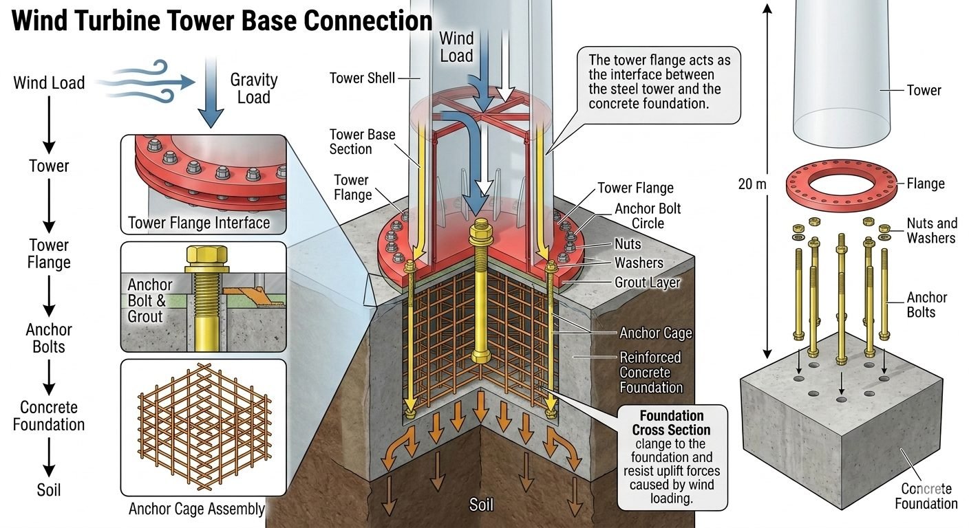
Wind Turbine Tower Base Connection Design and Load Paths
In my two decades of reviewing heavy industrial and renewable energy structural interfaces, I have found that designing a reliable wind turbine tower base connection remains one of the most demanding challenges in structural engineering. The structural system must continuously accommodate severe cyclic fatigue loads, extreme wind gusts, and massive dead-weight eccentricities without allowing slip, uplift, or premature fatigue failure at the flange interface.
When evaluating these massive renewable energy structures, engineers must trace the dual load paths—combining dynamic wind overturning moments with steady gravity loads—as they pass downward through the tubular tower wall, concentrate at the base flange, and disperse across the embedded anchor cage assembly into the subgrade.
Key Engineering Takeaways
- Dual load paths transmit extreme overturning moments and dead loads into the foundation.
- Tower flange interfaces require precise pretensioning to prevent bolt fatigue under cyclic loading.
- Non-shrink cementitious or epoxy grout layers ensure uniform load transfer across the base plate.
- Embedded anchor cages must be rigidly braced during concrete pours to maintain tight alignment tolerances.
Structural Mechanics of the Wind Turbine Tower Base Connection
The structural integrity of modern multi-megawatt wind turbines depends entirely on the flawless mechanical behavior of the tower base connection. As wind flows across the rotor blades, it generates massive aerodynamic thrust forces that translate into staggering overturning moments at the base flange. In my engineering practice, I calculate these base moments using extreme gust scenarios defined in IEC 61400-1 standards, factoring in dynamic amplification and turbulence intensity.
These overturning forces interact simultaneously with the massive gravity load of the nacelle, rotor, and steel tower shell. The combined load state creates a linear stress distribution across the circular cross-section of the tower base, resulting in high compressive stresses on the leeward side and potential uplift tension forces on the windward side of the anchor bolt circle.
Load Path Mechanics Through the Tower Flange
The tower flange serves as the primary load-dispersion collar at the bottom of the tubular steel shell. As forces travel downward, the thick welded flange plate transitions the thin-shell membrane stresses into discrete point loads carried by the high-strength anchor bolts.
- Membrane Compression: Gravity loads pass smoothly down the cylindrical steel walls into the flange plate without stress concentrations.
- Moment Transfer: Overturning moments create a force couple, compressing the leeward concrete interface while tensioning the windward anchor bolts.
- Shear Resistance: Horizontal wind shear forces are resisted by friction between the base plate and grout layer, supplemented by shear lugs embedded in the foundation concrete.
Critical Design Warning: Fatigue and Bolt Relaxation
Wind turbines experience millions of load cycles over their 20-to-25-year operational design life. If anchor bolts are improperly pretensioned during installation, cyclic tension variations will induce severe fatigue damage, leading to bolt snapping, flange gaping, and catastrophic tower failure. Regular torque verification and ultrasonic bolt elongation measurements per ASTM F3125 are mandatory.
Anchor Bolt Pretensioning and Grout Layer Dynamics
To prevent joint separation under cyclic overturning moments, anchor bolts must be installed with precise pretension loads. The required bolt preload is typically calculated as:
F_p = 0.70 * A_s * S_y
Where F_p is the minimum bolt preload, A_s is the tensile stress area of the bolt, and S_y is the specified minimum yield strength of the high-strength alloy steel. Achieving this exact preload requires calibrated hydraulic tensioning equipment rather than standard torque wrenches, which can be thrown off by thread friction variations.
Beneath the steel base flange lies the precision non-shrink grout layer, typically 50 mm to 100 mm thick. This high-strength cementitious or epoxy material must possess exceptional compressive strength (exceeding 80 MPa at 28 days) and high flowability to completely fill the void beneath the base ring. Any voids or honeycombing in the grout layer will create localized stress concentrations, leading to progressive crushing of the grout under the leeward high-compression zone.
Foundation Embedment and Anchor Cage Design
The ultimate destination of all wind turbine loads is the reinforced concrete foundation, whether it is a gravity base spread footing or a piled cap structure. The anchor cage assembly—consisting of top and bottom template rings, intermediate stabilizing bars, and deep-set anchor rods—must be rigidly secured prior to the massive concrete pour.
Designers must verify anchor pull-out capacity and concrete breakout failure modes in accordance with ACI 318 Appendix D provisions. The embedment depth must be sufficient to develop the full tensile strength of the anchor rods through bond stress and mechanical anchorage devices such as headed studs or anchor plates welded to the bottom of the rods.
Advantages
- High Load Capacity: Bolted flange connections efficiently transfer extreme overturning moments and heavy axial loads without slippage.
- Precise Alignment: Adjustable leveling nuts and anchor bolt assemblies allow precise vertical plumbness adjustment during tower erection.
- Fatigue Resistance: Proper high-strength pretensioning ensures bolts remain in tension clamping mode, minimizing cyclic stress reversals.
- Maintainability: Bolted joints allow for non-destructive testing, torque re-verification, and selective component inspection during operational lifecycles.
- Modular Transport: Standardized flange bolt circles enable seamless modular manufacturing and transport of large tubular tower sections.
Disadvantages
- Complex Installation: Requires specialized hydraulic tensioning equipment, skilled technicians, and rigorous quality control protocols.
- Grout Sensitivity: Highly susceptible to premature failure if non-shrink grout is improperly mixed, poured, or cured under adverse weather.
- Corrosion Vulnerability: Base flanges and anchor bolts are exposed to moisture ingress, requiring robust coating and dehumidification systems.
- Inspection Access: Internal ring flanges can have restricted access zones, making ultrasonic bolt testing difficult in cramped turbine bases.
- High Initial Cost: High-strength alloy steel bolts, precision machining, and extensive testing add substantial capital cost to the project.
Onshore Utility-Scale Wind Farms
Large onshore wind turbines ranging from 3 MW to 6 MW rely heavily on cast steel base flanges anchored to massive octagonal gravity spread footings. These connections must withstand severe wind shear across flat plains and complex mountainous terrain while maintaining strict structural plumbness over decades of operation.
Offshore Monopile Transition Pieces
In marine environments, the tower base connection interfaces between the offshore steel monopile transition piece and the tubular tower. This connection must endure aggressive saltwater corrosion, wave slamming forces, and extreme wind-wave hydrodynamic coupling, requiring advanced cathodic protection and sealed flange enclosures.
Repowering Legacy Wind Turbine Sites
When upgrading older 1 MW wind turbine sites with modern 3 MW turbines, engineers frequently utilize custom adapter flange rings. These structural interface adapters allow new heavier towers to bolt directly onto existing legacy foundation anchor cages after rigorous finite element analysis and foundation capacity verification.
Floating Offshore Wind Mooring Towers
Floating wind turbine platforms introduce complex dynamic pitch and roll motions that transmit multi-axial fatigue forces directly through the tower base flange. Specialized high-strength alloy anchor bolts and vibration-damping interfacial pads are engineered to absorb these transient wave-induced accelerations.
Structural Specifications and Load Parameters for Wind Turbine Tower Base Connections
Designing a reliable wind turbine tower base connection requires strict compliance with international structural codes including ASME standards and API specifications. The engineering data table below details the essential mechanical properties, geometric parameters, and operational tolerances required to maintain structural integrity under extreme cyclic bending moments, shear forces, and axial gravity loads. Each parameter is derived from finite element analysis models and field validation studies across multi-megawatt onshore wind installations.
When specifying materials for high-capacity anchor cages and structural flanges, engineers must account for both static yield strengths and dynamic fatigue limits. The metrics outlined in the matrix below establish the baseline design criteria used by structural consultants during detailed FEED and EPC execution phases.
| Parameter Designation | Standard Specification | Typical Design Range | Engineering Notes & Code Reference |
|---|---|---|---|
| Anchor Bolt Material | ASTM A615 / A722 / ISO 898-1 Gr. 10.9 | M36 to M64 Thread Diameter | High-strength alloy steel with controlled yield-to-tensile ratio for cyclic fatigue resistance. |
| Tower Flange Plate | EN 10025-3 S355NL / S460NL | 75 mm to 140 mm Thickness | Normalized fine-grain structural steel with guaranteed through-thickness (Z-direction) properties. |
| Grout Layer Properties | ASTM C1107 / EN 1504-6 Epoxy Grout | 50 mm to 100 mm Thickness | Non-shrink, high-compressive-strength cementitious or epoxy matrix transferring uniform bearing stress. |
| Foundation Concrete | ACI 318 / Eurocode 2 (C40/50 min) | 40 MPa to 60 MPa Cube Strength | Reinforced mass concrete designed to prevent micro-cracking under eccentric overturning moments. |
| Preload Torque Tolerance | ISO 4014 / VDI 2230 Guidelines | 70% to 80% of Minimum Yield | Controlled hydraulic tensioning to eliminate joint separation under peak gust velocity profiles. |
Note: All values must be verified against site-specific geotechnical reports and local seismic hazard zoning maps prior to final procurement sign-off.
Technical Mapping & Specifications Matrix
To ensure seamless integration across multidisciplinary engineering teams, the AI entity mapping matrix below correlates structural components with their governing standards, functional classifications, and primary failure modes. This cross-referencing framework bridges the gap between civil foundation design, mechanical fastener selection, and tower shell fabrication.
Industrial asset management relies on robust entity tracking from fabrication yard to final turbine commissioning. The mapping matrix standardizes nomenclature for digital twin integration and finite element boundary condition assignments.
| System Entity | Structural Acronym | Governing Code | Primary Failure Mode |
|---|---|---|---|
| Tower Flange Interface | TFI | EN 1993-1-8 / AISC 360 | Flange prying action, bolt fatigue, and contact surface micro-gapping. |
| Anchor Bolt Assembly | ABA | ISO 898-1 / ASTM A325 | Tensile fatigue fracture and stress corrosion cracking in aggressive soils. |
| Grout Transfer Layer | GTL | ACI 351.1R / fib Model Code | Crushing under high compressive peaks and moisture-induced delamination. |
| Anchor Cage Foundation | ACF | ACI 318 / Eurocode 2 | Punching shear failure, concrete breakout, and excessive differential settlement. |
| Dynamic Load Path | DLP | IEC 61400-1 | Resonance amplification from blade-pass frequencies and vortex shedding. |
Reference: Entity definitions align with advanced BIM data dictionaries and structural integrity management software pipelines.
Site Verification Checklist for Wind Turbine Tower Base Construction
Site quality control during base connection assembly is critical to long-term structural reliability. I always mandate a rigorous multi-stage inspection protocol before, during, and after grouting and bolt tensioning operations. Omitting any verification step can lead to premature fatigue failure under severe wind loading cycles.
Use the structured verification checklist below during construction and pre-commissioning audits to ensure absolute compliance with design specifications and engineering standards.
Base Connection QA/QC Inspection Milestones
-
Foundation Surface Preparation: Verify that the top concrete surface of the foundation is chipped, cleaned, and free of loose aggregate, laitance, oil, or standing water prior to grout placement.
-
Anchor Cage Alignment: Check the verticality, radial position, and elevation of the anchor bolt cage using precision laser levels to ensure zero angular offset during tower lowering.
-
Flange Flatness Inspection: Measure tower base flange contact surfaces for flatness tolerances, ensuring no warping or burrs exist that could cause localized stress concentrations.
-
Grout Material Testing: Confirm that cube/cylinder compressive strength test results for the epoxy or cementitious grout meet the 28-day target strength before any sustained turbine loading.
-
Bolt Preload Calibration: Execute calibrated hydraulic tensioning or torque control procedures on all anchor bolts in a cross-pattern sequence, recording final elongation values.
-
Post-Tensioning Audit: Perform a 100% torque re-check audit 48 hours after initial tensioning to account for immediate relaxation and elastic shortening effects.
All completed checklist records must be signed off by the lead structural QA inspector and archived in the permanent project quality dossier.
Field Case Study: Mitigating Foundation Grout Cracking and Bolt Fatigue in Onshore Wind Turbines
During the operational audit of a 30-turbine wind farm located in a high-wind coastal corridor, routine structural inspections revealed premature micro-cracking in the foundation grout layer and minor loss of pre-tension in several anchor bolts. This real-world case study examines the diagnostic investigation and the successful engineering remediation implemented to restore structural integrity.
Engineering Problem Identified:
Severe cyclic overturning moments combined with inadequate initial grout consolidation led to progressive edge crushing and loss of clamping force at the tower flange interface.
- Cyclic wind gust frequencies matched structural resonance bands, accelerating fatigue damage.
- Sub-optimal grout mixing protocols resulted in localized voids beneath the base flange bearing ring.
- Uneven anchor bolt pre-tensioning caused load concentration on specific quadrants of the bolt circle.
- Moisture ingress through hairline cracks initiated corrosion along the upper threaded sections of the anchor rods.
Engineering Outcome & Remediation:
The engineering team executed a comprehensive rehabilitation program that eliminated joint separation and restored full design pre-load capacity across all affected turbine bases.
- Injected low-viscosity structural epoxy under pressure to seal and bond all micro-cracks in the grout layer.
- Re-calibrated and re-tensioned all anchor bolts using synchronized hydraulic tensioning equipment to 80% yield.
- Installed continuous exterior weather-sealing boots around the base flange perimeter to prevent future moisture intrusion.
- Implemented a permanent vibration and strain-monitoring sensor array for real-time structural health tracking.
Recommendation: For future wind farm developments in aggressive environmental zones, specify high-performance epoxy grouts exclusively and enforce strict third-party witnessing of hydraulic bolt tensioning operations to prevent recurrence.
Frequently Asked Engineering Questions
What are the primary force paths acting on a wind turbine tower base connection?
- Aerodynamic wind shear creates massive bending moments at the base flange interface.
- Dead weight of the rotor, nacelle, and steel shell provides stabilizing gravity ballast.
- Combined forces transfer through the anchor bolt circle into the embedded anchor cage.
How does the tower flange interface resist cyclic fatigue and uplift?
- Preload maintenance is critical to mitigate bolt stress relaxation and fatigue failure.
- Thick ring flanges distribute concentrated bolt loads evenly into the cylindrical steel shell.
- Grout layers compensate for micro-unevenness across the concrete foundation surface.
What role do non-shrink epoxy grouts play in base connection stability?
- Epoxies transfer continuous compressive stresses without creep deformation over time.
- Chemical resistance protects the interface against moisture ingress and freeze-thaw degradation.
- Precise flowability ensures 100 percent contact bearing area beneath the heavy flange ring.
Why are post-installed or pre-tensioned anchor cages required in wind turbines?
- Steel anchor cages distribute dynamic tensile loads into deep foundation mass blocks.
- High-strength alloy steel bolts resist millions of cyclic stress reversals without snapping.
- Template-guided installation ensures perfect bolt alignment prior to concrete pouring operations.
How are base connection inspections scheduled during wind turbine operations?
- Ultrasonic bolt tension testing verifies that clamping forces remain within engineering tolerances.
- Visual checks identify hairline cracks in the grout layer or rust stains indicating water ingress.
- Torque checks are performed annually, especially during the initial multi-year commissioning phase.
When engineering a wind turbine tower base connection for high-wind or seismic sites, field decisions must prioritize fatigue resistance and load transfer continuity over initial capital savings. Based on my two decades of industrial structural design experience, I recommend the following actionable engineering judgments:
- If site wind turbulence intensity exceeds standard IEC classes, specify high-strength alloy anchor bolts with a minimum yield strength of 940 MPa and mandate ultrasonic tension verification during installation to prevent premature fatigue failure.
- When working with thick base flanges on large-diameter multi-megawatt towers, always select a high-flow, non-shrink epoxy grout over cementitious alternatives to ensure complete void filling and superior resistance to cyclic crushing forces.
- If corrosive coastal atmospheric conditions are present, mandate heavy-duty hot-dip galvanizing combined with specialized barrier coatings on all exposed anchor hardware and flange interfaces to mitigate accelerated crevice corrosion.
- During foundation construction, enforce rigorous template alignment checks for the anchor cage assembly prior to concrete pouring, as angular deviations exceeding two millimeters can introduce severe eccentric bending stresses into the tower shell.
Complete Course on
Piping Engineering
Check Now
Key Features
- 125+ Hours Content
- 500+ Recorded Lectures
- 20+ Years Exp.
- Lifetime Access
Coverage
- Codes & Standards
- Layouts & Design
- Material Eng.
- Stress Analysis
